Saturday 23 September 2017

WEEK 8 (FYP 2)


WEEK 8

                   Activity: LM35 Interfacing With Arduino...How it Work?


                  Today blog I will explain about the LM35 interfacing with the Arduino. Learning something new is quite interesting okay...When talking about LM35 that's means this component is related with the temperature sensor. So below is the LM35 picture. For your information, this is the 4th Experiment that I do for my FYP Project is Development of Home Automation System Using Android with Smartphones Application.


LM35 Temperature Sensor

LM35 SIMPLE INTRODUCTION
  • Having an analog output voltage proportional to the temperature is the LM35.
  • Output analog voltage can be converted to digital via the ADC
  • No any external calibration circuitry and provide output voltage in Celsius.
  • When temperature is increases, then the output voltage also increases and the sensitivity of LM35 is up to 10mV/degree Celsius.
  • The temperature ranging from -55 to 150 Celsius with 3 terminal sensor is used.
  • One of the advantages is the temperature output of LM35 is more precise than the thermistor output. As you can see the pin description at above. 

PIN DESCRIPTION


  • GND: Ground
  • VCC: Supply Voltage from (3.3V - 30V)
  • OUT: Gives analog output voltage to proportional to the temperature (in Celsius)
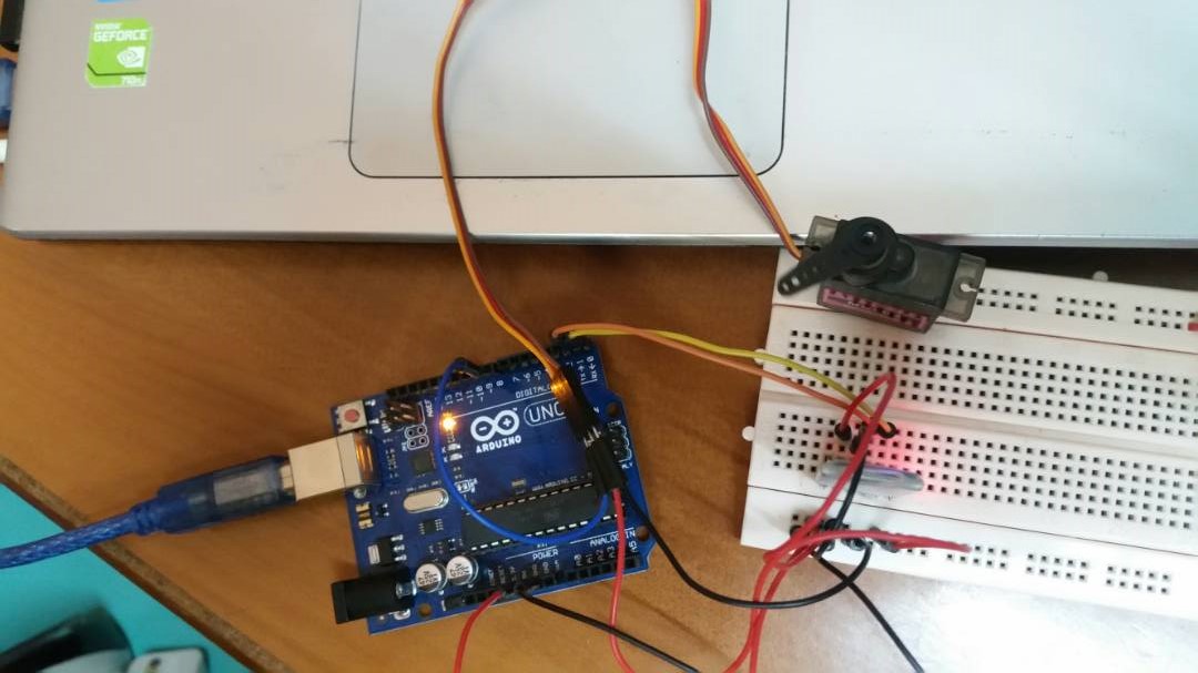
INTERFACING DIAGRAM

Interfacing LM35 with Arduino Nodemcu

After connect the power supply on Nodemcu, then upload the coding of LM35 and the serial monitor will displaying all the measuring og surrounding. Based on the above picture, the Arduino UNO has been replace to the Nodemcu which is change it to the small component and the interesting is this Nodemcu is completely with the Wi-Fi.


Coding From Temperature Measurement

Based on the picture coding above, you can see the arrow. Both arrow is the 'auth token' (can get from the email) and the 'ssid' and 'password'. Need to fill all of this instead of coding to run this experiment.


Result from Blynk Apps

Refer to the picture above, is the result from Android Application "BLYNK".  As you can see the reading show is the ADC Value. Here the LM35 output is given to analog pin A0 of Nodemcu.


Coding LM35

Based on the Picture above, is the coding to get LM35 data via the blynk apps. For this case, I will prove the output on BLYNK apps is correct with this calculation.

CASE 1: 

       resolution = Vref / 1024
where; 
       Vref = 3.3V 
       = 3.3V / 1024 
       temperature = (analog voltage * resolution) * 100 
where; 
       = (89 * 0.003222) * 100  
       = 0.2868 * 100  
       = 28.68 Celsius
       
Based on the calculation, the value in Celsius show is 28.68 and the serial monitor show the reading is 28 Celsius. meaning that, the value from serial monitor is more precise than the value of calculation.

UNTIL THEN...

THAT'S ALL FOR THIS WEEK..WAIT MY ANOTHER BLOG PROGRESS FOR MY FYP PROJECT. ASSALAMUALAIKUM...
       
☺ ☺ ☺ ☺ ☺


Saturday 16 September 2017

WEEK 7 (FYP 2)


WEEK 7

            Activity:  Servo Motor Interfacing With Arduino UNO....How It Work?


Movement of object can be controlled by controlling motor movement. Normally in robotics projects, servo motor control mechanism is very useful controlling position robotics. In this week's blog..I write and testing about servo motor control using Arduino UNO. Keep read my blog and I will explain more detail about the servo motor.:D:D


SERVO MOTOR?


SG-90 (Servo motor for motorized curtain)                      MG90S (Servo motor for open/close door)

Specification connection


Because of the name is motor...so that the servo motor in the way to control the position of objects. It is easily to control the physical movement of any object because due to the easily position controlled feature. Servo motor cannot move in direct position because it is rotate along in angle range which is 0 to 90 degree, 0 to 180 degree, and also 0 to 360 degree. Servo motor have many apply in robotics project as well.  Because the feature, servo motor is very easy with the connection of Arduino or any others micro-controller in order to built some project as my final year project which is Development of Home Automation System using Android with Smartphone/Mobile Application.


 Running servo motor to control door

Running servo motor to motorized curtain


Saturday 9 September 2017

WEEK 6 (FYP 2)


WEEK 6

                Activity: 2nd Briefing (Introduction, Literature Review, and Methodology)


              In this week, the briefing was conducted in TTL and as usuall, all the attandance of all FYP 2 student is compulsory. The briefing was by  Miss Pusparini Dewi Abd. Aziz.

           DATE: 6TH SEPTEMBER 2017
           VENUE: TTL 2
           TIME: 3PM - 5PM


In this briefing, the FYP committees have been brief us about:

HOW TO WRITE A STRONG THESIS STATEMENT....
  • understand the academic writing task.
  • Familiar with the different kinds of thesis statements.
  • Formulate a research question.
  • Formulate a tentative thesis statement.
  • Examine a contradiction.
  • Write a thesis statement as a complex sentences and, 
  • Test the thesis statement by considering the following questions.


Sunday 3 September 2017

WEEK 5 (FYP 2)


WEEK 5


      Activity: PIR Motion Sensor (Experiment 2)


Assalamualaikum...

      As shown as today, is the week fifth i'm gonna try to explain some experiment about the PIR Motion Sensor (HC-SR501). 
All experiment that I do were related with my Final Year Project which is DEVELOPMENT OF HOME AUTOMATION SYSTEM USING ANDROID WITH MOBILE APPLICATION.


WHAT IS A PIR MOTION SENSOR

      A PIR sensor is one that detect movement in a limited range and normally around 7 feet for the cheaper sensor like I used for this project HAHAHAHA. This sensor sense movement by detecting patches of infrared radiation in front of it. 

    PIR sensor are more complicated than many of the other sensors because there are multiple variables that affect the sensors input and output. The IR sensor itself is housed in a hermetically sealed metal can to improve noise, temperature, humidity immunity. There are small, inexpensive, low-power, easy to use and don't wear out. 

     There is a body made of IR-trans-massive material (typically coated silicon since that is very easy to come by) that protects the sensing element. Behind the body are the two balanced sensors. This small thing are normally referred to as PIR "Passive Infrared" or "IR Motion" sensor.


HOW IT WORK..

When a warm body like human or animal passes by, meaning that for the animal not for the small one okay... it first intercepts one half of the sensor, then it will causes a positive differential change between the two halves. The reverse happens when the warm body leaves the sensing area whereby the sensor generates a negative diff. change.So...this is what will happen on the PIR sensor....
For now..already know the basic knowledge of these kinds of sensor...


REQUIRED MATERIALS:
  • Arduino Uno
  • Breadboard (for this experiment)
  • PIR Motion Sensor (HC-SR501)
  • LED
  • Buzzer (also can be added)
  • Amount of jumper wires 


Circuit Diagram (Based on Proteus Software) and the Codes (Arduino) just email me....azlina.aminah@yahoo.com


☺☺☺☺☺☺☺☺


 PART 1


PART 2


If you guys like my projects and if there any addition or any comment, please LIKE my videos so that i understand they are helpful and keep going for new projects :)

Here on YouTube Channel also..

Good Luck, Have Fun!!  ;D;D;D;D;D